
- PROLIFIC USB TO SERIAL COMM PORT USE WITH ARDUINO HOW TO
- PROLIFIC USB TO SERIAL COMM PORT USE WITH ARDUINO DRIVER
- PROLIFIC USB TO SERIAL COMM PORT USE WITH ARDUINO PRO
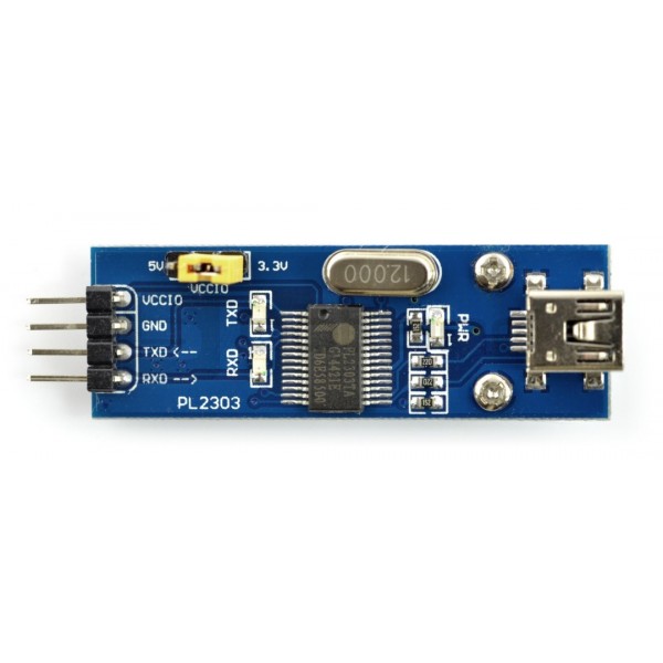
I used a small piece of raw circuit board and I cut the copper to make some simple tracks. Next step was to build the connector for the development board. I proceeded by moving yellow RTS wire to DTR pad. Second, on the red wire, there are 5 V, not 3.3 V and the third is that RxD is pulled up to 5 V. First of all, the DTR pad is not connected to a wire. On the right side, there is the TTL serial port, with the following configuration. In the above photo, on the left side there is the USB port, with GND at the top, near the LED and VCC 5 V at bottom. Instead, the 5 V USB voltage, passed through a small value resistor, was available at the other end of the cable. The internal 3.3 V regulator can supply no more than 4 mA, so it wasn't an option to power the development board from it. More than that I found out it used 3.3 V levels (the chip includes 5 V to 3.3 V regulator and supports 1.8 V to 3.3 V signal levels). With the help of the multimeter and chip datasheet I identified the pins. To my luck, it contained something that looked like a rather generic PL-2303 PCB with pads on two opposite sides, for the USB port and for the serial port.

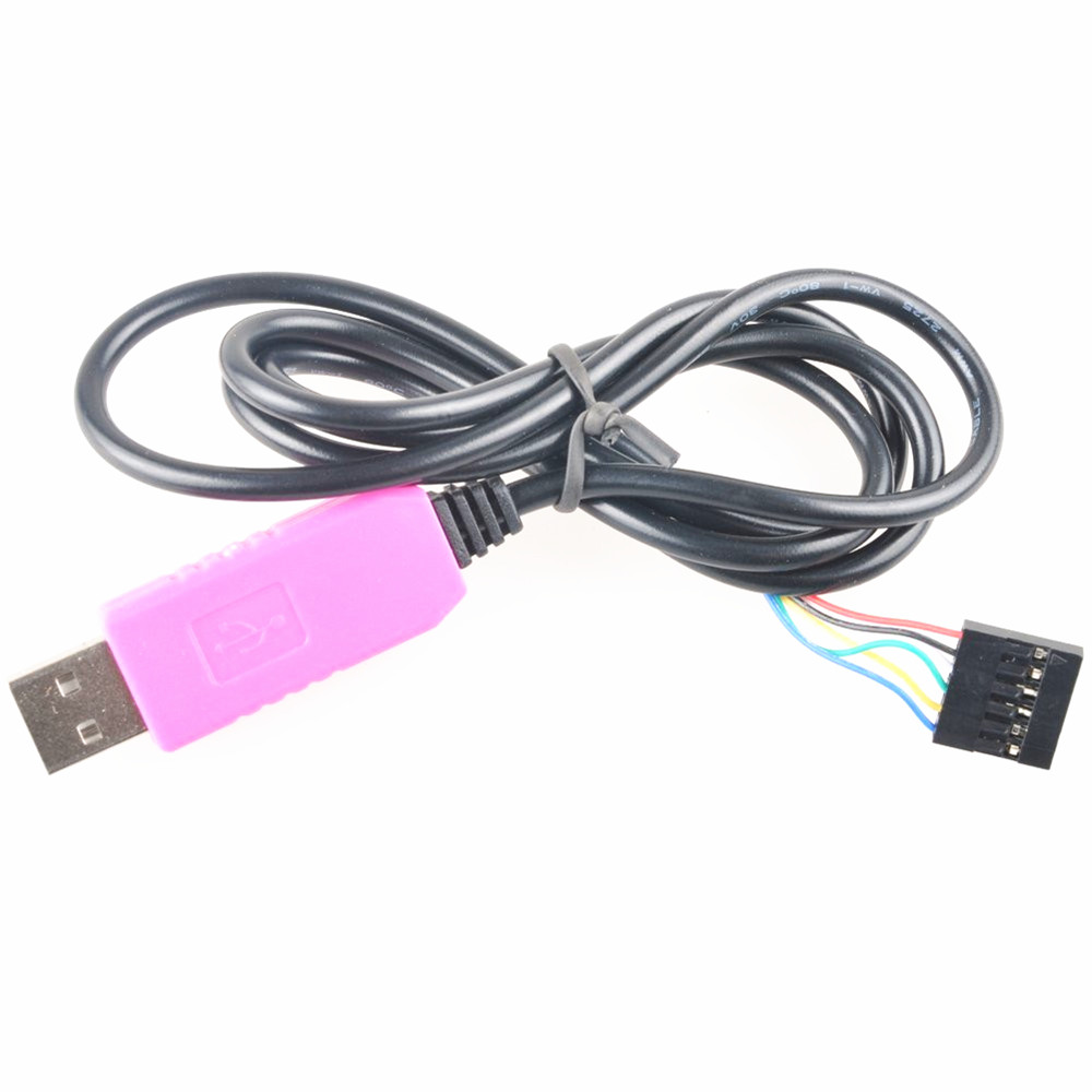
Knowing this, I opened the plastic case across the old phone cable. I don't know what voltage levels those two use or if they have a level switch.Īnyway, getting back to my situation, I needed to provide the development board with: 3.3 V supply and ground, Rx and Tx lines and DTR signal.
PROLIFIC USB TO SERIAL COMM PORT USE WITH ARDUINO PRO
The recommended adapter which matches pin to pin with Arduino Pro Mini serial port is based on FT232 and CP2102. Soldering a wire directly to the DTR pin chip could be a valid option, but I didn't want to modify the adapter. The pin exists at the chip, but it is not wired to the pinheader. This is missing to the cheap CH340G adapters. Besides that, DTR signal is wired to MCU reset, triggering the bootloader to allow data download to board. Data is transferred using Rx and Tx lines. To program any Arduino board using the bootloader a serial port is used. PL2303 Serial Adapter for Arduino Pro Mini I remembered I had some old USB phone cables with included USB-RS232 converter so I decided to make my own adapter to program the 3.3 V Pro Mini board. The price of such a converter is not a problem, but having to wait for a month or so to be delivered is a problem. All I own were CH340G with Tx and Rx lines only and the CH341A programmer locked to 5 V levels. This means that in order to program this board, I needed such a converter.Īnd I realized I didn't have a suitable one just when the development board arrived. There is no USB to serial TTL converter chip. Since the board will be plugged into a PCB, I choose the Arduino Pro Mini compatible design, which is just the MCU with a few external parts that are required for proper functionality. I got a 3.3 V Atmega328p development board for a project.
PROLIFIC USB TO SERIAL COMM PORT USE WITH ARDUINO DRIVER
Get the right driver for this chip to make it work on Windows 10
PROLIFIC USB TO SERIAL COMM PORT USE WITH ARDUINO HOW TO
How to use PL-2303HX USB serial adapter to program Arduino Pro Mini.


 0 kommentar(er)
